

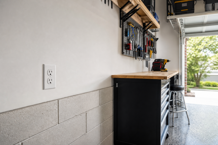
Taking on the project to add electrical outlets to garage walls rewards careful planning and patience. Rushed work leads to results that need redoing within a year. A methodical approach delivers results that hold up for years.
This guide covers every stage from preparation to completion, with specific details on materials, tools, measurements, and techniques. Follow the sequence for the best outcome.
Understanding Electrical Load and Circuit Requirements
A 20-amp, 120V circuit safely delivers about 1,920 watts continuously (80% of 2,400W max). If your table saw pulls 1,800 watts and the shop vac draws 1,200 watts, they can’t run on the same circuit simultaneously without tripping the breaker.
GFCI protection is code-required for all garage outlets. These devices trip at small current leaks (typically 4-6 milliamps), preventing electrocution in damp conditions. In garages, trips can be caused by moisture, cold temperatures, or brief startup surges from motor-driven tools.
Most garages were wired with one or two 20-amp circuits, enough for basic lighting and an outlet. Power tools, compressors, heaters, and EV chargers easily exceed that original capacity. For EV charging specifically, check out our detailed garage EV charging station installation guide for proper electrical requirements.
Calculate your actual needs before running wire. List every tool and device you’ll plug in, note the amperage or wattage (check the nameplate or manual), and group items by where you’ll use them. A workbench area might need two separate 20-amp circuits if you regularly run multiple tools. A charging station for battery-powered tools can share a circuit with general lighting.
Standard 12-gauge wire handles 20-amp circuits. For 15-amp circuits, 14-gauge is acceptable but 12-gauge offers future flexibility at minimal extra cost. Buy 25-foot spools for short runs, 100-foot spools for whole-garage projects. Romex (NM-B cable) works for most applications. Exposed wire in unfinished areas requires conduit protection in many jurisdictions.
Planning Your Outlet Layout
Space outlets 4 feet apart along workbench walls. This spacing means you’ll always have a plug within reach without dragging extension cords. For open wall sections without workbenches, 6-foot spacing works for general use.
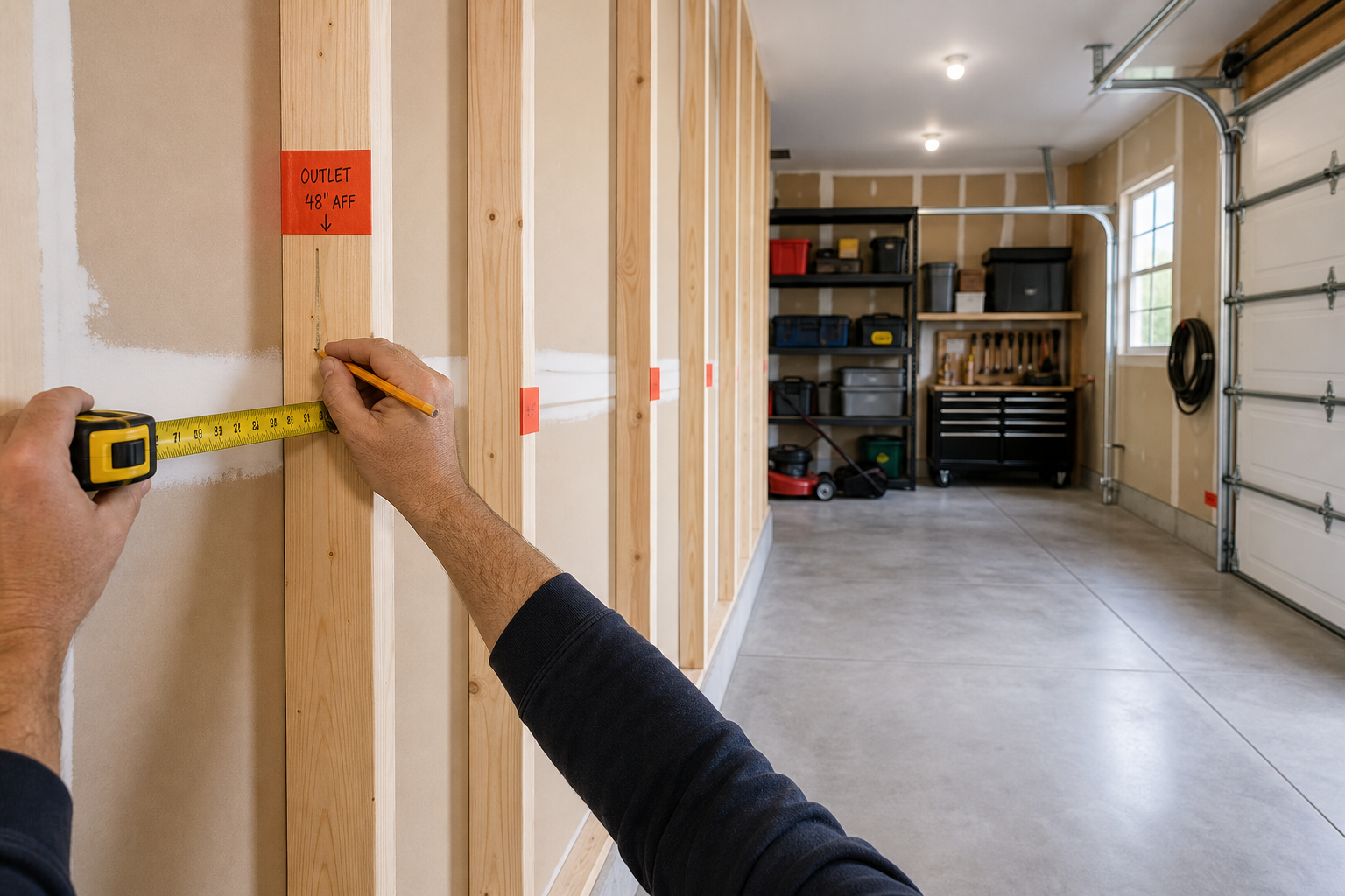
Height matters for function. Standard outlets sit 12-18 inches above the floor, matching interior room height. In garages, mounting at 48 inches (countertop height) keeps plugs accessible when you’re working standing up and prevents bending to plug in bench tools. Floor-level outlets collect dust and risk water contact during cleanup or leaks.
Mark outlet locations with painter’s tape before buying materials. Live with the layout for a few days. Plug tools in where you actually use them. Move the tape if the spacing doesn’t match reality. This costs nothing and prevents permanent installations in the wrong spots.
Consider future needs during layout. An empty wall today might hold a new workbench next year. Adding an extra outlet while the wire is exposed and you’re already working costs far less than opening walls later.
Outdoor-rated boxes (NEMA 3R or better) work well in unheated garages where condensation occurs. The gaskets and weatherproof covers prevent moisture from reaching connections. Standard interior boxes work in climate-controlled garages but can develop corrosion issues over time in humid conditions.
Running Conduit and GFCI Protection
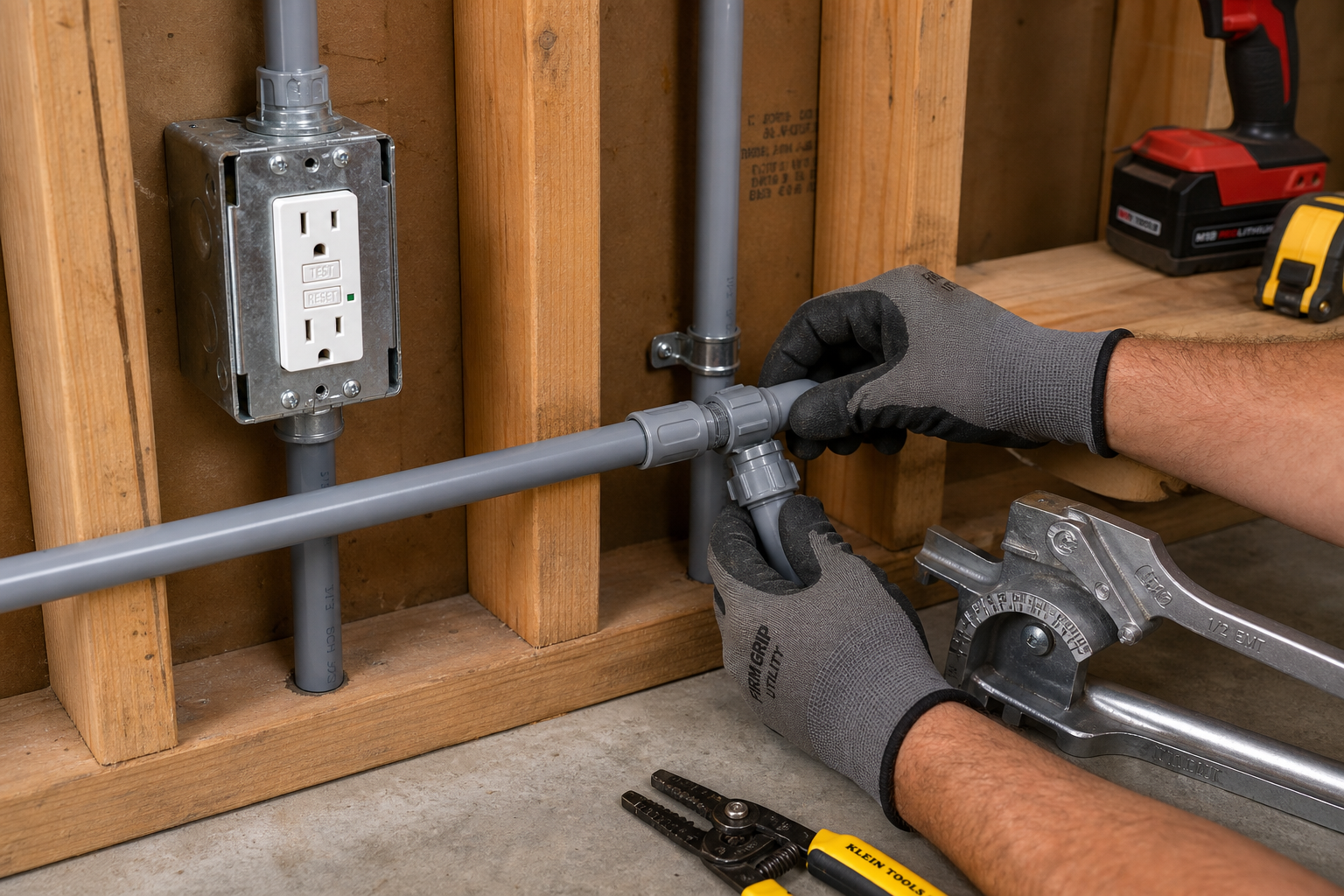
EMT (electrical metallic tubing) conduit is the cleanest approach for surface-mounted runs. The thin-wall steel tubing bends with a hand bender, mounts to studs or concrete with one-hole straps, and looks professional when runs are straight and level.
PVC conduit costs less and resists corrosion but looks less finished in visible areas. It’s the better choice for underground runs (from main panel to detached garage) or anywhere moisture is constant. Schedule 40 PVC is code-minimum for most applications. Schedule 80 adds impact resistance for exposed areas where you might hit it with equipment.
Measure the entire run before cutting anything. Add 10% for connections and corners. A 30-foot straight run needs 33 feet of conduit to account for the material inside junction boxes and couplings.
Use a hand bender for 90-degree corners in EMT. Mark the conduit, align the bender arrow with your mark, and apply steady pressure until the bend reaches 90 degrees. Check with a level. Practice bends on scrap before working with your final runs. Kinked conduit gets scrapped.
GFCI protection works two ways: GFCI breakers at the panel or GFCI outlets as the first device on each circuit. GFCI breakers protect everything downstream. GFCI outlets protect only what’s plugged into them plus any standard outlets wired to the load terminals. For a single circuit with multiple outlets, one GFCI outlet at the first box protects everything downstream and saves money versus multiple GFCI outlets.
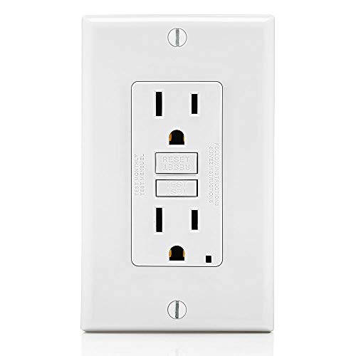
GFCI Outlets
Essential for code compliance and safety in all garage electrical installations
Wire the GFCI correctly. Incoming power connects to the LINE terminals (usually marked with tape or a different color). Outgoing wire to downstream outlets connects to LOAD terminals. Reversing these connections means the GFCI won’t protect anything. Test with the test button before closing up boxes.
Mount junction boxes to studs with screws, not just the box’s built-in nails. Two screws per box into solid wood creates a rigid mount that won’t shift when you plug and unplug heavy tools. For concrete or block walls, use tapcon screws or hammer-set anchors rated for the box weight plus wire pull forces.
Working with 20-Amp and 240V Circuits
20-amp circuits require 12-gauge wire and 20-amp rated outlets. These outlets have a T-shaped neutral slot that accepts both standard 15-amp plugs and 20-amp plugs. Don’t install 15-amp outlets on 20-amp circuits. The outlet becomes the weak point and can overheat under sustained high loads.
20-amp circuits make sense for workbench areas, anywhere you’ll run table saws, routers, planers, or multiple tools simultaneously. The extra capacity prevents nuisance tripping when running multiple tools.
240V circuits (for welders, compressors, large air conditioners, EV chargers) use thicker wire (10 AWG for 30A, 6 AWG for 50A) and double-pole breakers. A 240V/30A circuit delivers 7,200 watts continuously, enough for a serious welder or a Level 2 EV charger drawing 24 amps.
Installation of 240V circuits typically requires a permit and licensed electrician unless you have substantial electrical experience and your jurisdiction allows homeowner electrical work. The wire is expensive (6 AWG runs several dollars per foot), the breakers are costly, and mistakes create fire hazards. Hire this out unless you’ve done it before.
Dedicated circuits prevent problems. An air compressor that cycles on while you’re running a table saw won’t trip the breaker if each tool has its own circuit. A garage refrigerator or freezer should always run on a dedicated circuit so power tools don’t affect it.
Permits, Inspections, and Safety
Most jurisdictions require permits for new circuits, panel upgrades, and any 240V installation. Pull the permit before starting work. Expect a plan review (submit a simple drawing showing circuit routes, outlet locations, and wire gauges) and at least one inspection after rough-in before you close walls.
Permit fees typically range from modest to moderate depending on project scope. The inspection catches mistakes before they’re buried in walls. Unpermitted work creates problems when selling the house. Some buyers walk away, others demand professional rewiring at your expense, and all of them use it to negotiate price down.
Shut off power at the main panel before opening any electrical box or working with wire. Use a non-contact voltage tester to verify power is off. Test the tester on a known live circuit first to confirm it’s working. Touching a live 120V circuit is painful. Touching 240V can stop your heart.
Work during daylight or set up temporary lighting that runs from a different circuit. Headlamps and flashlights free both hands and put light exactly where you’re looking. Cheap clip lights cast shadows in the wrong places.
Keep a fire extinguisher rated for electrical fires (Class C) in the garage. Mount it near the exit, not near the panel where a fire might block access to it.
Materials Checklist and Tool Requirements
You’ll need wire (12-gauge Romex for 20-amp circuits), outlet boxes (plastic for drywall, metal for exposed or conduit runs), GFCI outlets, standard 20-amp outlets, wire connectors (yellow for 12-gauge), cable staples, conduit and fittings if running surface-mount, box extenders if adding outlets to existing shallow boxes, wire strippers, voltage tester, drill with bits for running wire through studs, stud finder, tape measure, level, and screwdrivers.
Material costs for a typical project adding four outlets on one new circuit remain reasonable. That includes 100 feet of 12-2 Romex, four boxes, one GFCI outlet, three standard outlets, a 20-amp breaker, connectors and staples, and consumables. Double that for two circuits. Add more for conduit runs using EMT.

Electrical Panel Labels
Professional labeling prevents confusion and helps during future maintenance
Rent a fish tape if running wire through finished walls. The rental beats spending hours trying to push wire blindly. For open stud walls, drill 3/4-inch holes through stud centers at the same height and push wire through by hand.
Step-by-Step Installation Process
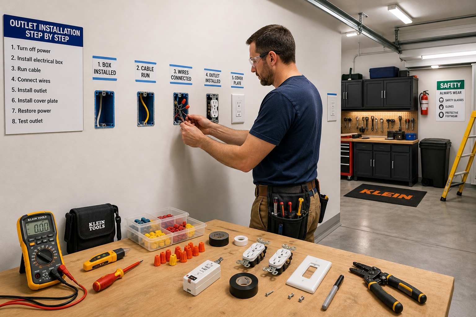
Start at the panel. Verify you have space for new breakers. A full panel means adding a sub-panel or upgrading the main panel, both jobs that require an electrician unless you’re experienced.
Run wire from the panel to the first outlet box. Leave 12-16 inches of extra wire at each box for connections. Excess wire tucks into the box. Short wire means rerunning the whole circuit.
Staple Romex every 4.5 feet along the run and within 12 inches of each box. This meets code and prevents sagging wire. Don’t overtighten staples. Crushing the cable damages the insulation inside.
Strip 6-8 inches of outer sheathing from the cable at each box. Strip 3/4 inch of insulation from each individual wire. Too much exposed copper creates a shock hazard. Too little and you can’t get a solid connection.
Making Proper Wire Connections
Connect ground wires first (bare copper). Twist all ground wires together (incoming cable, outgoing cable, pigtail to the outlet, pigtail to the metal box if required), add a wire connector, and tug each wire to confirm the connection is solid. Connect the ground pigtail to the green screw on the outlet.
Connect neutral wires (white). Twist together, add connector, tug test. Connect the neutral pigtail to the silver screw on the outlet.
Connect hot wires (black). Same process. Connect the hot pigtail to the brass screw on the outlet.
For GFCI outlets, pay attention to LINE and LOAD. Incoming power goes to LINE. Outgoing wire to the next outlet goes to LOAD. Standard outlets downstream will be GFCI-protected without being GFCI outlets themselves.
Final Assembly and Testing
Fold wires into the box carefully. Don’t just cram them. Hot and neutral wires shouldn’t cross or touch. Ground wires can overlap. Screw the outlet to the box, install the cover plate, and move to the next box.
At the panel, connect the new circuit. Turn off the main breaker first. Connect the white neutral to the neutral bus bar (the bar with all the white wires). Connect the ground to the ground bus bar (usually the same bar in a main panel, a separate bar in a sub-panel). Connect the black hot wire to the new breaker, snap the breaker into the bus bar slot, and label the breaker clearly at the panel.
Turn on the main breaker. Turn on the new circuit breaker. Test each outlet with a plug-in tester (the three-light device that shows correct wiring, open ground, reversed polarity, and other faults). Test the GFCI by pressing the test button. The outlet should click off. Press reset. It should click back on. If it doesn’t reset, check your LINE/LOAD connections.
Common Mistakes and How to Avoid Them
Undersizing wire for the load creates a fire hazard. Always match wire gauge to the breaker size (14-gauge for 15-amp, 12-gauge for 20-amp, 10-gauge for 30-amp). Going larger is fine. Going smaller is dangerous.
Installing outlets upside down (ground pin on top) looks wrong and makes plugging in large transformer blocks awkward. Ground pin down is the standard orientation for all outlets except those controlled by wall switches, which sometimes mount ground-up to indicate switch control.
Overloading outlet boxes causes connection failures. A standard single-gang box holds one outlet, one incoming cable, and one outgoing cable comfortably. Adding more cables requires a larger box or a junction box to split the circuit. Count wires: each conductor (hot, neutral, ground) counts as one, all ground wires together count as one, each device (outlet, switch) counts as two, and each cable clamp counts as one. Multiply by the wire gauge’s volume (12-gauge is 2.25 cubic inches per conductor). The box must have at least that total volume.
Forgetting to photograph wire routing before closing walls makes troubleshooting impossible later. Take clear photos showing wire paths, especially where they pass through or around obstacles. Date the photos and store them with your home records.
Mixing up neutral wires from different circuits in a shared box causes GFCI nuisance tripping and code violations. Each circuit’s neutral must stay with its own hot wire throughout the entire run. Use wire labels or different colored electrical tape on the sheathing if multiple circuits pass through one box.
Maintenance and Long-Term Performance
Test GFCI outlets monthly. Press the test button, verify it trips, press reset, verify it resets. A GFCI that won’t trip or won’t reset has failed and needs replacement. These devices wear out over time, especially in garages with temperature extremes.
Check outlet connections annually. Turn off the circuit, remove the cover plate, and gently tug each wire at its terminal. Loose connections create heat, which creates more looseness, which eventually creates arcing and fire. Tighten any loose terminals and verify connections are still solid.
Look for discolored outlets or cover plates. Brown or black marks around the slots indicate arcing or overheating. Replace the outlet immediately and investigate why it overheated (overloaded circuit, loose connection, damaged wire, or faulty outlet).
Outdoor-rated outlets in unheated garages may develop corrosion over years. The weatherproof covers slow this but don’t stop it entirely. Replace corroded outlets before they fail. Clean metal contact points with fine sandpaper or a wire brush before installing the new outlet.
Label circuits clearly at the panel and keep the labels updated. “Garage outlets” tells you nothing when half the garage is dark. “Garage north wall workbench” or “Garage west wall and lights” actually helps during troubleshooting.
Planning Your Garage Workshop Power Setup
A well-planned electrical system supports whatever you want to do in your garage. Whether you’re setting up a complete workshop space, creating a
